By James Philip
When placing a curved wall under stairs in Revit the option to edit profile is not available as in straight walls, when the wall is selected. See Fig 1

Fig 1
So one way to trim the top of the wall to the underside of the stair is to create a void to trim it. This is done using model in place.
On the Architecture tab select the drop down arrow beneath component and choose Model in place. See Fig 2

Fig 2
The Family Category and Parameters dialogue appears. Choose walls and select OK. See Fig 3

Fig 3
Name the object walls 1 and select OK. See Fig 4

Fig 4
You are now in the modelling environment, so select void forms, then Void sweep from the drop down list. See Fig 5
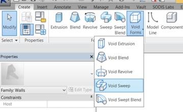
Fig 5
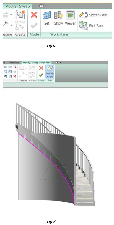
Choose the pick path button and select the underside of the stringer for the 3D path. See Figs 6 & 7
Select the green tick to accept the 3D path. Choose the modify sweep tab. Then pick the edit profile button. See Fig 8
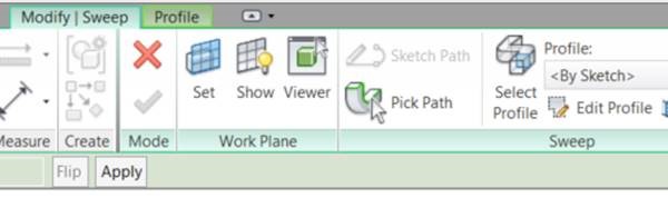
Fig 8
Choose the viewer button, this will make creating the profile a lot simpler. See Fig 9

Fig 9
In the viewer draw your profile as shown make sure it is wide and tall enough to cut away the top of the wall. The select the green tick and close the Viewer. See Fig 10

Fig 10
Select the Modify Sweep tab and pick the green tick. See Fig 11

Fig 11
On the ribbon pick the cut tool, then select the wall and then the void. See Fig 12
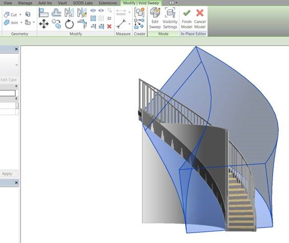
Fig 12
The wall is trimmed, so select the green tick to complete the process. See Fig 13
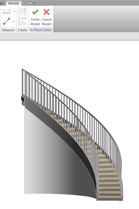
Fig 13
When placing a curved wall under stairs in Revit the option to edit profile is not available as in straight walls, when the wall is selected. See Fig 14
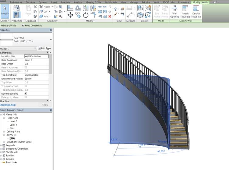 Fig 14
So one way to trim the top of the wall to the underside of the stair is to create a void to trim it. This is done using model in place.
On the Architecture tab select the drop down arrow beneath component and choose Model in place. See Fig 15
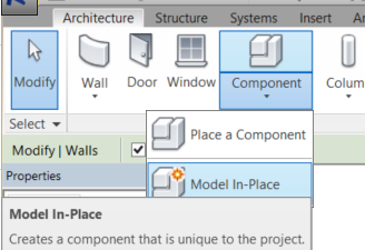
Fig 15
The Family Category and Parameters dialogue appears. Choose walls and select OK. See Fig 16
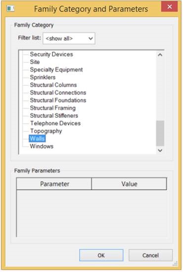
Fig 16
Name the object walls 1 and select OK. See Fig 17
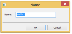
Fig 17
You are now in the modelling environment, so select void forms, then Void sweep from the drop down list. See Fig 18

Fig 18
Choose the pick path button and select the underside of the stringer for the 3D path. See Figs 19 & 20
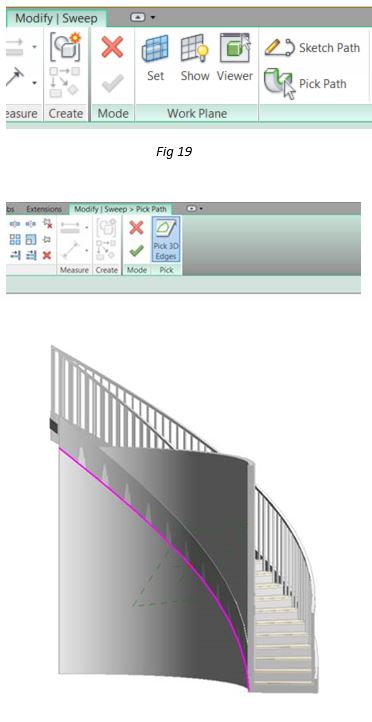
Fig 20
Select the green tick to accept the 3D path. Choose the modify sweep tab. Then pick the edit profile button. See Fig 21
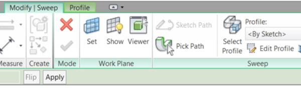
Fig 21
Choose the viewer button, this will make creating the profile a lot simpler. See Fig 22
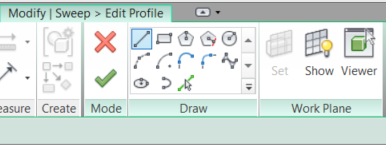
Fig 22
In the viewer draw your profile as shown make sure it is wide and tall enough to cut away the top of the wall. The select the green tick and close the Viewer. See Fig 23
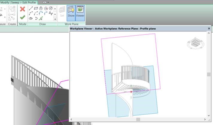 Fig 23
Select the Modify Sweep tab and pick the green tick. See Fig 24
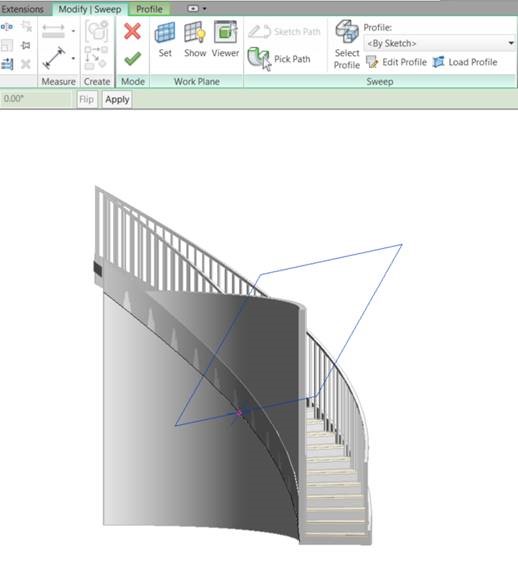
Fig 24
On the ribbon pick the cut tool, then select the wall and then the void. See Fig 25

Fig 25
The wall is trimmed, so select the green tick to complete the process. See Fig 26

Fig 26
Visit Cadline Community for more blogs.