By Luke Howell
I’m often asked how to create vertical faces in a surface or how to create a Retaining Wall feature.
Now there are a few different methods, using different tools in Civil 3D, the most common is building it into your corridor assemblies, but what if you don’t have a corridor or that the Retaining Wall isn’t perpendicular to the design?
I have seen this overcome by offsetting the feature by 0.001m (1mm) and then changing the elevation value and using both as a break line in the surface. This way will only give you a fixed line and commonly gives an error or broken surface due to the Surface properties.
In this example, we will make a grading style that can target an existing surface and provide a sheer/vertical face that will represent our retaining wall.
We will start by making a Grading Criteria specifically for Retaining Walls.
On the Setting Tab of the Prospector, Select Grading, Grading Criteria Set, Basic Set and any of the ‘Surface @ x:x Slope”.
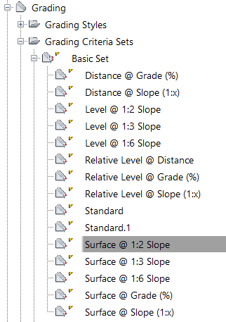
Right Click and Copy.
Rename – Retaining Wall
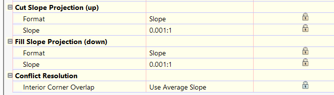
On the Criteria Tab, Change the Cut and Fill slope values to 0.001:1 and lock the value
Create your feature line and set the elevation required, e.g. Finished Floor Level (FFL) for a new house plot.
Select the Grading Tools and create a new Grading group, ensure that Automatic Surface Creation is turned on.
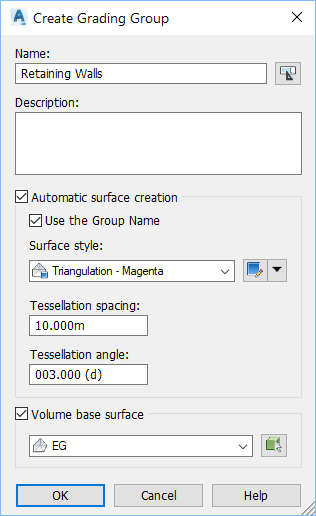
Make sure your target surface is set.
Select the Retaining Wall Grading Criteria and apply to the feature line where required.
If it is a closed Feature line, remember to set an Infill area.
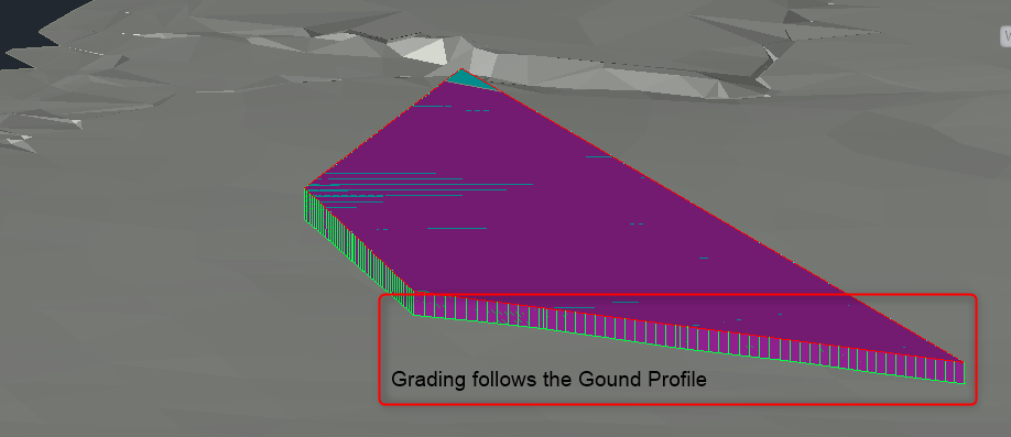
The Grading should take a near straight line to meet the Surface and create the desired sheer face/retaining wall.
Visit Cadline Community for more blogs.